Spii
Solo-built 500g sumo robot, designed and built independently.
Overview
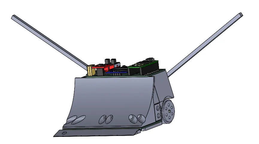
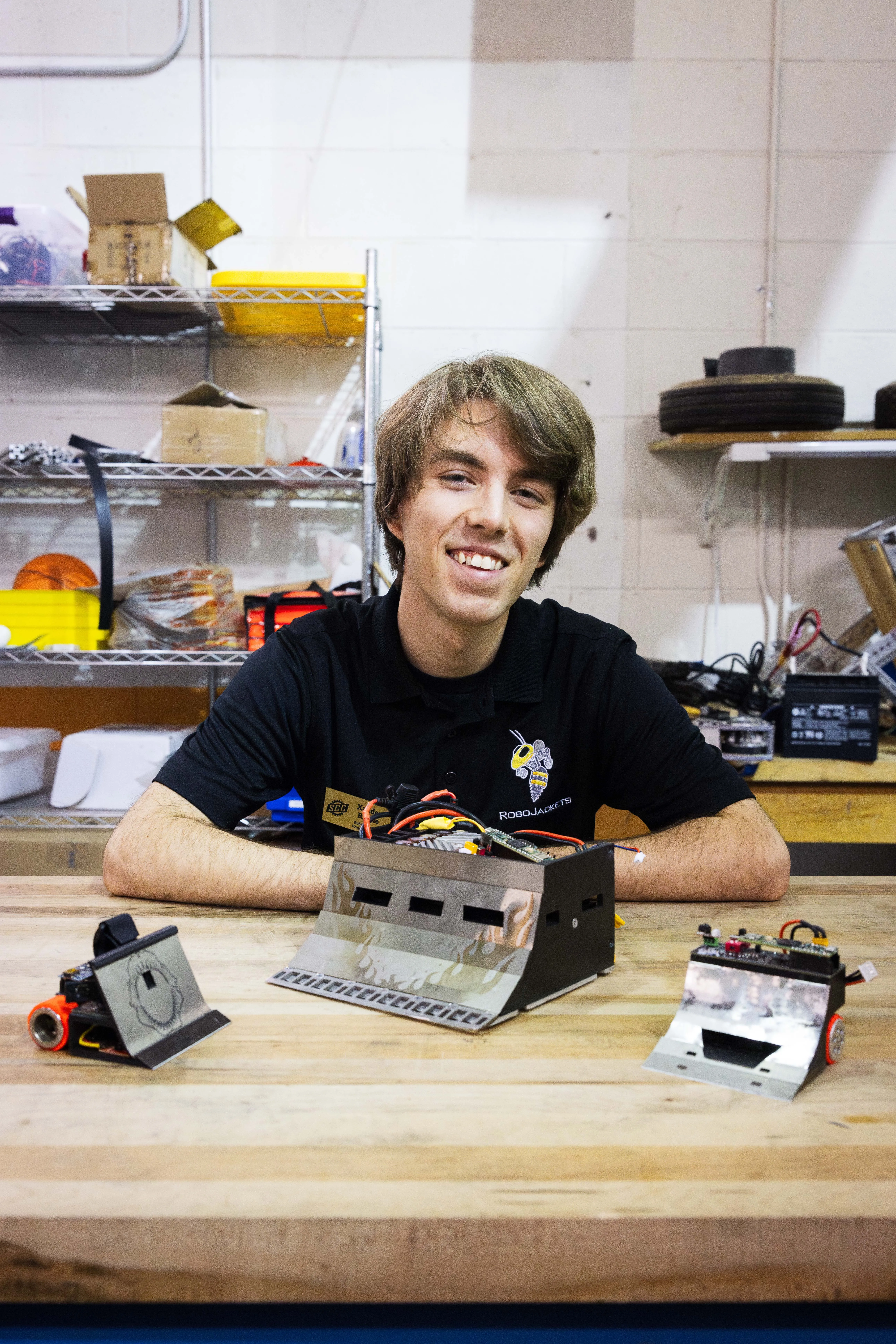
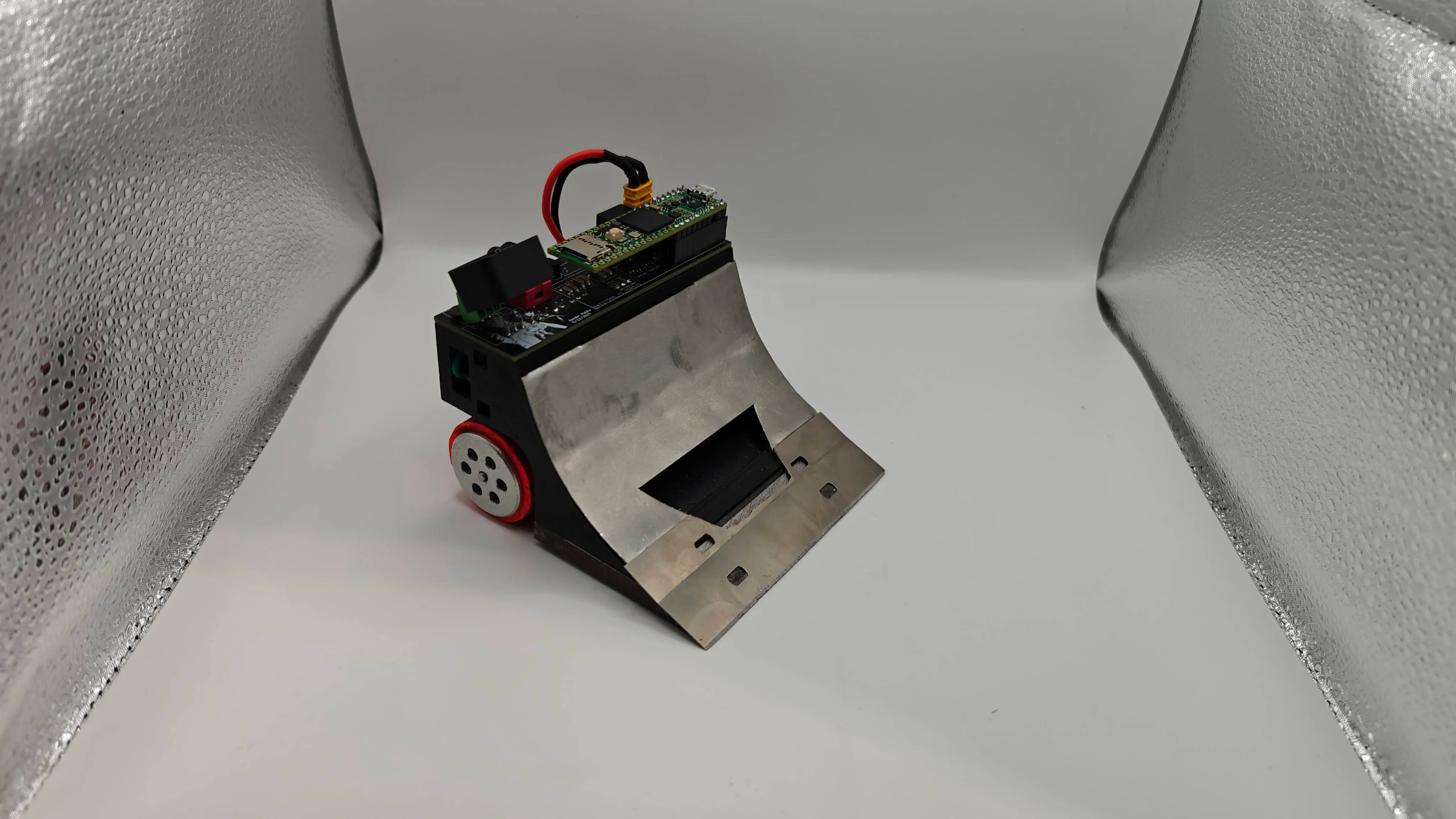
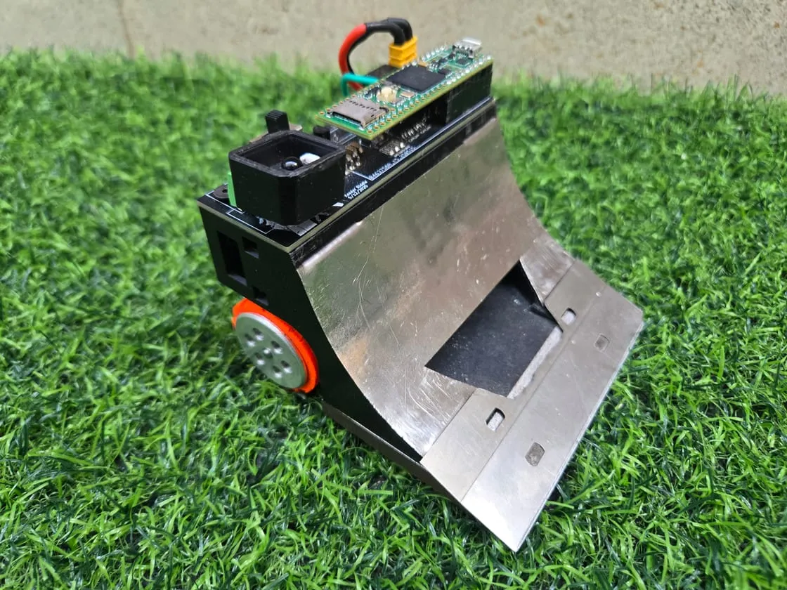
Spii is a 500g autonomous sumo robot, which means it competes in an autonomous form of combat robotics inspired by Japanese sumo wrestling where competitors fight to push each other out of a circular arena. I actually built Spii before I built Ferrarii, and through the process of building Spii I learned many of the tools necessary to attempt building a 3kg robot. Through Spii I learned KiCad, SolidWorks, and C++ primarily, along with some introduction to manufacturing and hardware. Inspired by a robot I saw in competition, I wanted to build a robot that would flip its opponents as it pushed them out. Thus, Spii was designed with a highly unconventional aggressive ramp that has proven effective time and time again. Spii has competed in many competitions, and attending such competitions has likely been a big source of inspiration towards my dedication to RoboWrestling.
- 2-2 @ RSM International 2026, São Paulo, Brazil
- 2nd @ 2026 Spring Jacket Racket, Atlanta, GA
- 4th @ Orlando Maker Faire 2025, Orlando, Florida
- 2-2 @ RoboChallenge 2024, Bucharest, Romania
Notably, RoboChallenge was my first international competition in robot sumo, and my first competition in robot sumo where I actually won a few matches. Additionally it was just really inspiring seeing all of the different robot designs and meeting all the competitors.
Technical Overview
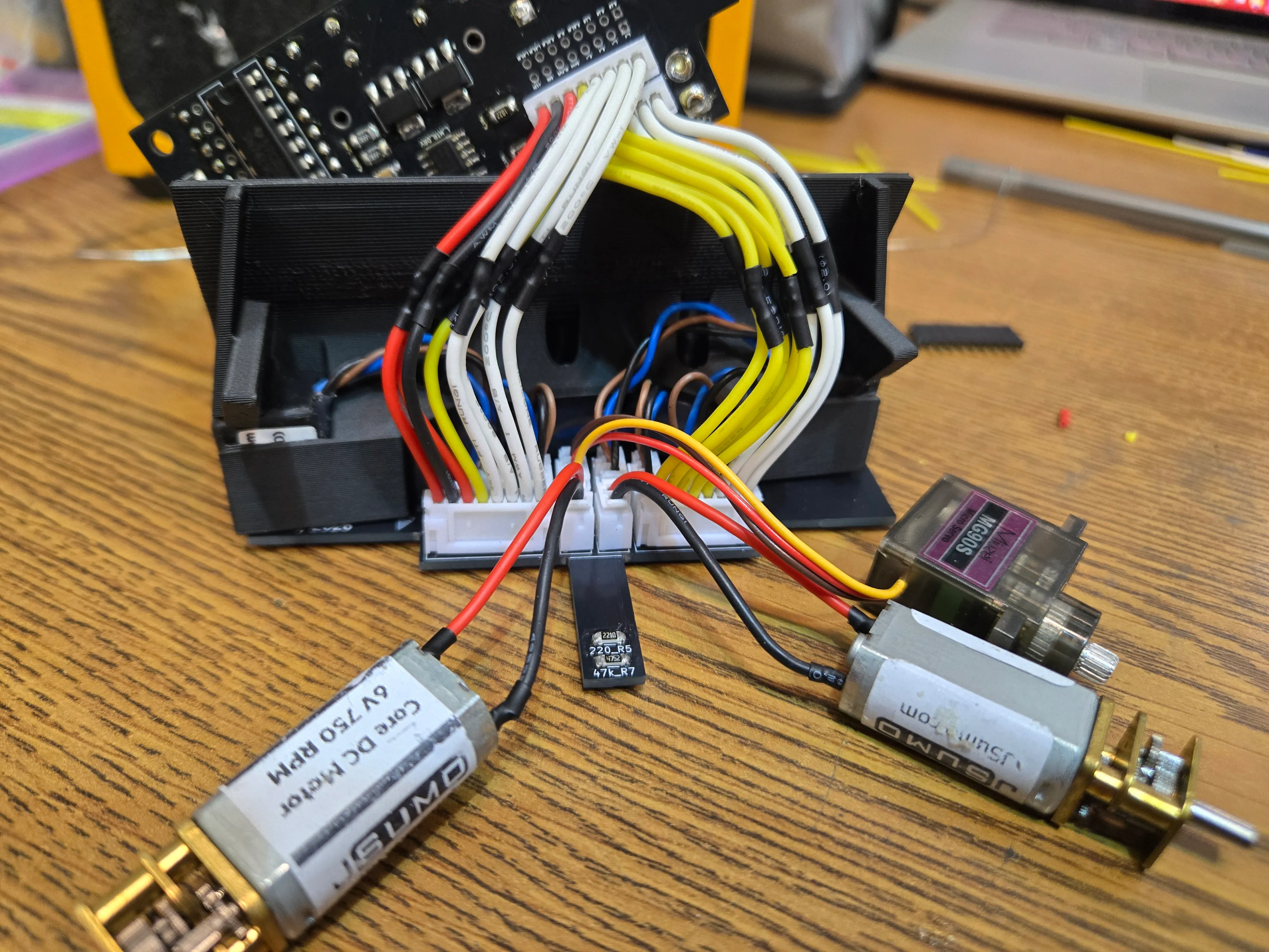
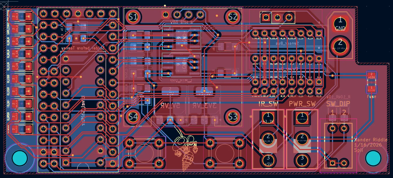
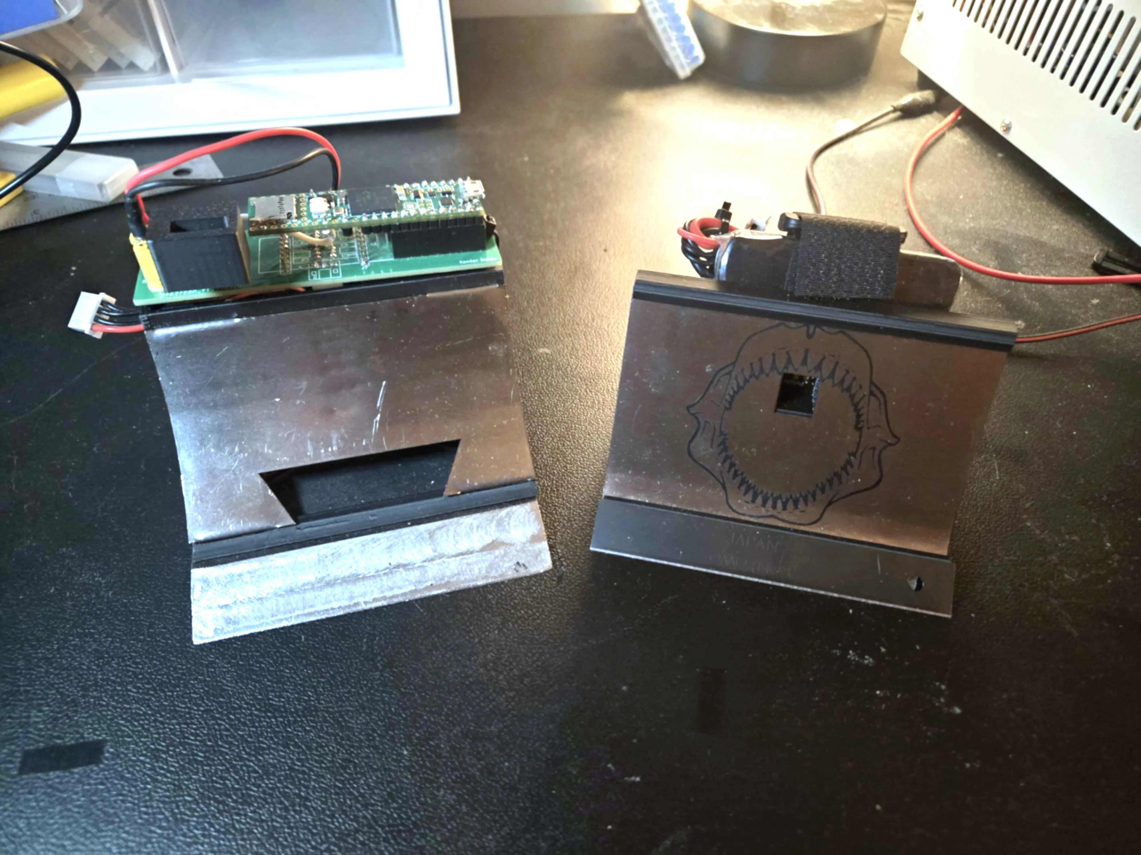
Spii is a 500g robot that has undergone a lot of iteration, but something that has always stuck is the ramp. Just like Ferrarii, Spii’s ramp poses a very difficult engineering problem, essentially halving the internal space from the get go. In the latest design of Spii, I must say I think I’ve outdone myself with compactness, and I was able to achieve such a feat by implementing a dual PCB design. Spii, taking inspiration from Ferrarii, also has a top PCB and a bottom PCB. The top PCB is strictly for human-robot interaction, while the bottom board hosts all of the sensors, of which there are a lot of. I was somehow able to fit 5 IR sensors, 3 line sensors, and a servo (and a LiPo battery) all within the robot by connecting all of the external sensors compactly into the floor PCB, and then using a main wire bus to route all the signals to the control PCB. Tis, some of my best wiring work. The code for this robot is available here.